"Electronic Hardware Design"

summary
Step-by-step account of building a conference badge that looks like a bow tie with LEDs and a microphone, from part selection to finished board: uses KiCad for schematic and layout, exports Gerbers and a BOM, orders parts immediately during shortages, assembles via breadboard then through-hole prototypes then SMT with a reflow oven and solder paste stencil, and uses interactive HTML BOM for placement. Final design has 30 unique parts (92 total) versus a simpler version with 4 unique (26 total). CircuitPython bootloader and firmware take roughly four days to debug after fixes for a mislabeled mic net and a reversed power part; the bow tie works after those fixes.
AI-written summary · about
chapters (18)
- 0:00Introduction to talk
- 0:47Overview of electronic design
- 3:14Schematic capture basics
- 4:18Circuit board cross section
- 5:21PCB layout process
- 6:23Manufacturing and assembly
- 7:25Breadboard prototype example
- 8:47Through-hole PCB design
- 10:11Final badge design overview
- 11:34Surface mount bow tie badge
- 13:593D modeling and mechanical fit
- 14:21Reflow soldering techniques
- 15:23Assembly tools and tips
- 16:26Debugging and firmware challenges
- 17:29Common design mistakes
- 18:10Other hardware projects
- 19:35Resources and next steps
- 20:36Q&A session
related talks
 35mWe Built 2,000 Custom Electronic Badges for Our Developer Conference, Replay (Here's How)
 46mSwagbadge 101: Hardware and SAOs
 55mThe Process of Shipping Hardware Products: Hardware Tales for Software Engineers
- 46mSwagbadge 101: Hardware and SAOs
 31mMoving Electrons with Rust
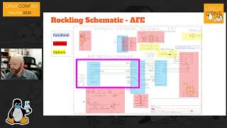 30mHardware design of the OHMC2022 Rockling & Swag Badge and OHMC close
 29mElectronic circuit design the FOSH way
 33mBuilding Open Hardware with FOSS